DJ Pi 1: analogue controls with Arduino
October 3, 2017
In this series of posts I’m going to document building a digital DJ effects box using a Raspberry Pi and Arduino. The inspiration for this project came from the combination of me having a crappy mixer with no built-in effects, a Pi and Arduino (both in need of a purpose) and a desire to learn more about audio programming and digital signal processing (DSP).
In terms of hardware I’ll be using the aforementioned Raspberry Pi 3 with this sound card to handle audio inputs and output and the Arduino Uno to handle the analogue control inputs. The Arduino side will be done in C, because it’s fun to program Arduinos in C, and the Pi app handling the actual audio processing will be in C++ because everyone seems to use it for audio DSP. I’m using the JUCE framework as an easy way in.
So, what’s the plan? First of all, I’ll describe how I’m using analogue potentiometers and digital buttons going through the Arduino’s analogue-to-digital converter (ADC) and digital input to control the effects box. Then, I’ll look at how to transmit these values to the C++ application running on the Pi. At this point I’ll figure out a nice structure for the C++ application.
With all that setup done the rest of the blog series should merely be the design and implementation of the actual effects components. I’ll probably start off with simple things like volume and delay before moving into the more exciting realms of DSP.
All of the code will be available on Github, in case you want to have a poke around. I’m going to assume you have some basic familiarity with the command line, C/C++ and programming on both the Raspberry Pi and Arduino. I’ll try and explain the low-level details of the Arduino that you might have missed if you’ve only written sketches in the Arduino IDE. I’ll also explain the audio processing bits more fully as the whole point of the project is for me to learn them well.
Where possible I’ll try to link to other resources that explain concepts clearly, rather than reinvent the wheel by writing my own incoherent explanations.
Arduino coding preliminaries
Hold your horses - there’s a little bit more to know about Arduino C programming before we jump in.
The Arduino is basically an AVR microcontroller (the ATmega328p in my Uno’s case) with a few extra bits and bobs attached to help beginners actually do something. So when looking for information on Arduino C programming it’s often more useful to look for AVR microcontroller resources rather than Arduino-specific stuff. I will probably use the terms “Arduino”, “AVR” and “microcontroller” fairly interchangeably. Sorry if that really annoys you.
If you’re interested in C programming on the Arduino (or any AVR microcontroller, I suppose), then I highly recommend the book Make: AVR Programming by Elliot Williams. It’s a comprehensive introduction to the capabilities of AVR microcontrollers such as the ATmega328p, combined with genuinely interesting project ideas. The Arduino code in this project is based on examples from the book. I also use the Makefile and some libraries provided by Williams here, which you’ll need in order to compile the code examples.
Seriously, check it now, it’s a great book.
Speaking of compiling code, you need a compiler and something to get the compiled code on to the Arduino. I’m using avr-gcc and avr-dude for this. See instructions for installing the toolchain at maxEmbedded here.
Getting set up
So, let’s think about what controls we want our effects box to have. For each effect we’ll want to have a knob that can control some kind of parameter and I think it would be useful also to have an off-on switch to toggle the effect. The knob will be a potentiometer, which expresses a range of values by varying an output voltage. This means it will output an analogue value. The switch will be a digital button, since it can only be in one of two states. My Arduino Uno has six analogue pins on it, so I guess we’ll have up to six effects (the buttons can connect to a digital pin instead). Each will have its own potentiometer and button so that it can be controlled independently of the others.
There are a number of ways to connect the Arduino to the Raspberry Pi. I’ll be using serial over USB because it’s simple and also powers the Arduino without having to worry about converting between different voltage levels (3.3v on the Pi, 5v on the Arduino).
For this post, let’s focus on just getting the Arduino to read an analogue value from a single potentiometer and output the value over the serial connection.
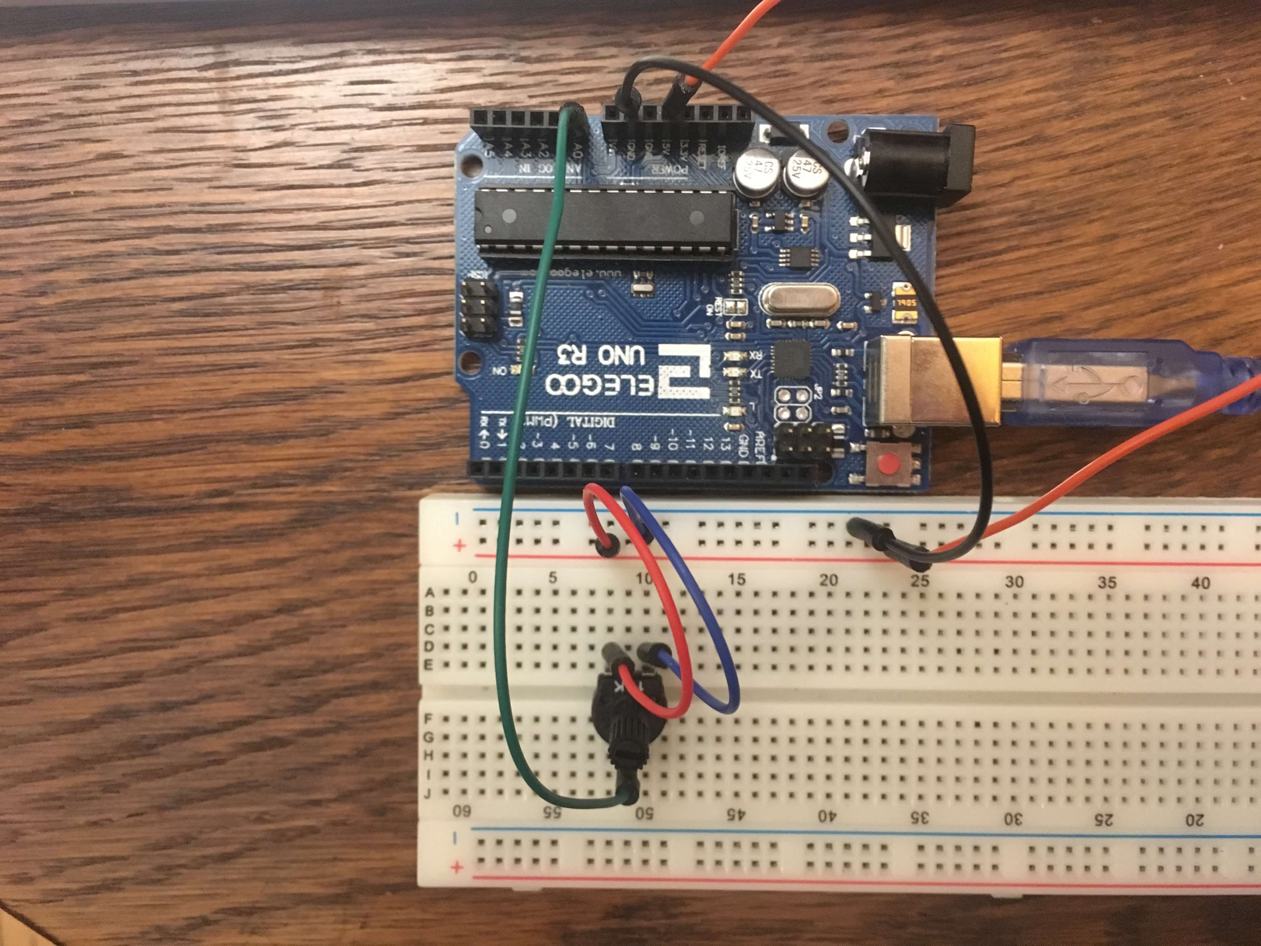
The code for this post is here. In terms of the circuit, you first need to connect the potentiometer to the 5V and GND pins. The output pin (probably the middle one) should go to the A0 analogue input pin on the Arduino.
Code walkthrough
If you’re writing a sketch in the Arduino IDE you use two key functions: setup() and loop(). The C code follows a similar pattern - some initialiation and then an endless loop. Before jumping into the details of what each line does, take a look at the overall structure. We have a few include statements, which pull in some useful library code. We define the function initFreeRunningADC. Note that this is the only function actually defined in the file - the rest are defined in the header files.
When the Arduino runs the code it starts by calling the main function. main calls a few initialiation functions (first the serial connection and then our ADC initialiser function) before entering an endless loop. The Arduino will continuously transmit a byte, wait five milliseconds and then start again. Because the loop is endless we never actually reach the return statement but it’s required to get the code to compile.
Configuring the ADC
Let’s dive into the initFreeRunningADC function. From its name we can tell that it’s initialising the ADC (or analogue-to-digital convertor) in free-running mode. The Arduino’s built-in ADC can run in a number of modes. Free-running mode means it’ll continuously output values.
Rather than regurgitate loads of information myself, I recommnend you read this blog post from Open Music Labs for further information on the inner workings of the ADC. The simple version is that the ADC periodically samples the analogue input its receiving and outputs a digital value representing the input at that moment in time.
Back to the code, we can see that we are making changes to a couple of variables called ADMUX and ADCSRA. These are defined in files included via the AVR library (#include <avr/io.h>) and refer to registers within the microcontroller. You can think of registers as sets of eight switches can be turned on (set to 1) or off (set to 0). As each register holds eight values the ATmega328p is an 8-bit microcontroller. The way to configure the various options within the Arduino is usually to set the corresponding bits in the correct registers.
maxEmbedded provides a good summary with some helpful diagrams.
You’ll see this |= (1 << XXX) syntax frequently. XXX will represent a numbered bit in the register, given a mnemonic to make it easier to remember. 1 << XXX tells us to take a 1 and shift it left however many number of times represented by XXX. This has the effect of setting that position in the register to 1. For example, if XXX was the third bit from the right, XXX would have a value of two and 1 << XXX would give you a value of 00000100. |= means to set the value of the register to its current value ORed with the new value. You go through both the current and new values and wherever either of them has a one you output a one, or a zero otherwise:
01010000 // value A
00000100 // value B
--------
01010100 // A | B (i.e. A OR B)
So the combined effect could be described as ’take bit XXX in the register and set it to 1, leaving the others as they were'.
ADMUX represents the ADC Multiplexer Selection register although, confusingly, only about half of its bits actually pertain to the multiplexer.
We tell the ADC to use the internal VCC for its reference voltage by putting a 1 into REFS0 and leaving REFS1 with a 0.
By default the ADC outputs a 10-bit value. In general we want this resolution but in this example we’ll be sending each value over the serial connection, which can only transmit one byte (8 bits) at a time. We could handle the conversion ourselves, but we can get the ADC to do it for us by setting the ADLAR bit. This causes the ADC to left-adjust the output so fit in a byte, stored in register ADCH. We’ll see later how to transmit values greater than 8 bits over serial. We could also write to bits 0-2 to choose which of the Arduino’s ADC inputs we are using, but because we’re using A0 (also known as ADC0) we don’t need to write any more bits to the multiplexer.
Next up is the ADCSRA, or Control and Status Register A. This register determines the functionality of the ADC. We set ADEN to actually enable the ADC (otherwise the ADC pins would just behave like normal pins), ADATE to set auto-trigger (i.e. free-running) mode and ADSC to start the first conversion. Our ADC is now reading and converting values!
In the main program loop we simply transmit the current value over serial (using a library function) and delay a few milliseconds. If you connect your Arduino to a computer and open a serial monitor on the Arduino’s serial device you should be able to see it continuously chugging away outputting the potentiometer’s value.
Reducing sample noise
There is one flag that I haven’t mentioned, which is setting ADPS2. The lower three bits of the register determine at what fraction of the microcontroller’s speed the ADC should operate. Setting ADPS2 to one and leaving the other two at zero corresponds to /16, or 1MHz assuming a 16MHz clock speed. The Open Music Labs article linked above has a super helpful graph showing how lower ADC clock frequencies result in less noise in the output signal. If you experiment with different prescaling values you should see that the output value bounces around a lot less as you increase the prescaler division factor. The sampling rate isn’t really an issue for us since humans are super slow at twisting potentiometers (from the Arduino’s point of view at least). But even with the largest prescaling value (128) we are still sampling over a hundred thousand times a second so it’s in the suitable range for sampling audio.
Things I’m unhappy about
This code is fine for demoing the ADC but there are a number of limitations that we’ll want to address before using this to actually control the effects box.
Only reads one input
Firstly, we’re not making use of the multiplexer so we can only read one analogue input. The choice of pin is also hardcoded by the choice of bits set in initFreeRunningADC, which isn’t very configurable.
Sends way too much data
Despite only reading one value, the code as written is pretty insistent about reading and transmitting this one value as many times as it can. OK, there’s a 5ms delay, so it’s only actually sending something 200 times per second, but this is way more than necessary.
Let’s think about what the C++ side of our application will have to do. It’ll be getting a constant stream of values through the serial interface. Each time a value comes over the wire it’ll have to check the value and decide what to do with it. But the vast majority of the values will just be duplicates of previous values, meaning that we’ll have to do loads of unnecessary work.
Rather than continuously output the state of the controls, we really want to just output any changes. This will reduce the amount of data coming down the wire and means that the C++ code will only have to deal with actually significant values.
Before we set off on our grand refactoring journey, let’s first take a look at what our C++ application actually needs to do to receive these values.