DJ Pi 3: improving Arduino code
October 8, 2017
So far in the blog series we’ve set up the basic hardware structure and got everything talking. The next step is to expand the Arduino code so that it can handle multiple controls and send more useful messages.
Remember that each virtual effect component running on the Pi will have a single potentiometer and button for control. I’m working on the basis that I’ll end up with six effects simply because my Arduino only has six analogue pins but the code will be able to handle more.
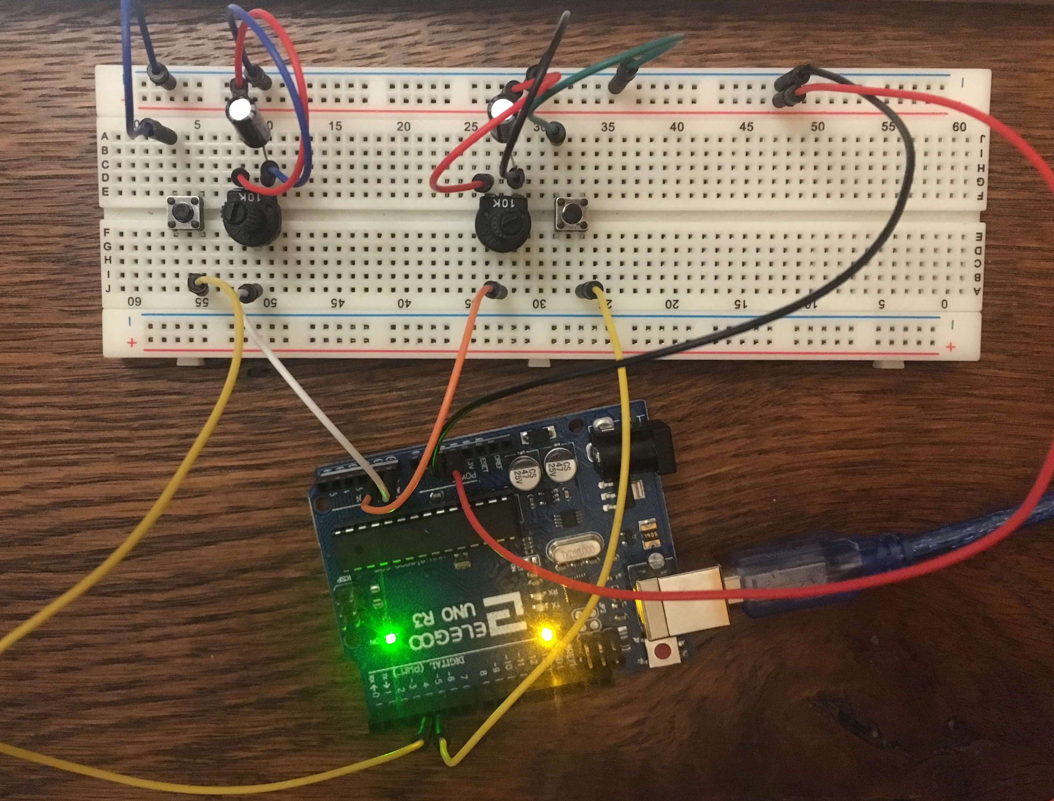
Here’s a photo of the circuit I’m working with. Note that I have added a capacitor between the inputs of each potentiometer to smooth the output a bit. Make sure you connect the button to correct input - it’s very confusing if you accidentally connect it to the other control’s button input!
Message format
Let’s consider what kind of messages we want the Arduino to transmit to the Pi. We’ll assume that all of the controls are off on start up.
- A button is pressed, enabling the control. The message should identify which control and include the potentiometer’s current value.
- A potentiometer value changes. The message should identify which control.
- A button is pressed, disabling the control. We still need to identify the control but no potentiometer value is included.
Clearly we’re going to need to transmit more than a single byte. Here’s the 16-bit format I settled on, copied from the pots.c source:
0000 00 0000000000
\    \  \
 \    \  10 bit ADC value
  \    01 indicates ON, ten lowest bits will be latest ADC value
    \  00 indicates OFF, ten lowest bits will be empty
      Four bit control identifier, start from 0000
And here’s an example of the intended output:
0011010000000000 <- ctrl 3 is ON and has value 0
0011010000000111 <- ctrl 3 is ON and has value 7
0011000000000000 <- ctrl 3 is OFF. Output from ctrl 3 will now stop
0011011111111111 <- ctrl 3 is ON and has value 0x3FF
Let’s go through this, starting from the right.
First we have the 10-bit output from the ADC. To get 10 bits we will need to make sure the ADLAR bit in the ADMUX register is disabled. The reasoning behind this is that we have an extra eight bits to fill and might as well use the full resolution available from the hardware.
Next we have bit 11, which indicates whether the control is on or off. Transmitting the current potentiometer value along with the ON signal seemed like the easiest way of making the sure the effects components know the value of the potentiometer when they need to. Note that the effects won’t be aware of any changes to the potentiometer when the control is off. This seemed unnecessary since they’ll be updated with the new value as soon as the control’s button is pressed and the control is toggled on again.
Note also that bit 12 isn’t actually used. I’m keeping it spare in case it proves useful later.
Finally we have the top four bits. These will identify which control is transmitting the message (they are numbered counting from zero). My Arduino only has six analogue pins but it seems that the Arduino Micro has the most of any Arduino with twelve. Allocating only three bits to the identifier, allowing for up to eight controls, therefore seemed a little limiting. Using four bits allows sixteen controls to hooked up. While I doubt I’ll ever have this many separate effects going at once, I can foresee having two potentiometers per effect.
Though the Arduino only has an 8-bit microprocessor it’s actually quite good at handling 16-bit values simply by using two registers. We just need to be careful to transmit the lower byte first due to serial being ordered least-significant byte first. You’ll see in a few places that I use an unsigned 16-bit integer (uint16_t), for example in the control IDs. This is so that they’ll map easily to the 16-bit output.
Code walkthrough
The Arduino code can be found in the usual repo. This code is quite a bit more complex than the previous example so I will just pick out the main points of interest rather than going through it line-by-line.
Note that definitions are moved out to pots.h. The pins used are also defined at the top of the implementation file, making things a bit more self-documenting than before.
As usual main does some initialisation and then enters an endless loop. We initialise the required number of controls and put them into an array. The main loop then cycles through each of those controls, checking for changes and responding accordingly.
I have tried to create at least a little bit of abstraction by creating the Control structs to represent each physical control. They in turn are made up of Button and Pot structs. You can see in newControl that I am using malloc to allocate them all on the heap and manipulate them via pointers. In a previous iteration I had just created them on the stack within newControl, thinking that it would return a copy of the created structs that could then be saved into the controls array. This didn’t work because creating the ctrl variable on line 141 creates a copy and changes made to it (e.g. toggling is_on) weren’t persisted to the next loop. I could have saved the modified ctrl back into the array at the end of the loop but it seemd cleaner to just use pointers and modify the structs directly.
Using the ADC
initADC should resemble its free-running cousin, initFreeRunningADC. The main differences are that we are setting the prescaler to /128 to reduce the amount of noise in the output. We are not setting ADATE so the ADC will not run in free-running mode.
Instead, we can see in readADC that we first specify the pin we want to read from and then enable the ADC by setting ADSC in ADCSRA. This one will remain there while the conversion is taking place. Once it’s done the bit is set back to zero and the value can be read. The loop_until_bit_is_clear function is a helpful library function from the AVR library.
Syntactically the only new thing is the & operator, known as bitwise AND. It goes through two sets of numbers and sets the output to one wherever both inputs are one:
11100000 // 0xe0
01100110 // let's assume ADMUX contains this bit sequence
--------
01100000 // top three bits copied and bottom five reset to zero
As you can see, this allows us to ‘copy’ over or reset bits. Each time we read from the ADC we need to use the MUX bits to specify which pin to read from. However, the bits in the register will already contain the bits used to specify the previous pin. We need to reset those bits to zero and then specify our new bit pattern. As it happens, only the bottom five bits in ADMUX are used to specify the correct pin. We don’t want to change the top three bits so we use the bitmask 0xe0 to ensure that the values held in the top three pins will be transferred to the new value.
Happily, the bit pattern needed to specify a particular pin is just the binary form of the pin number, ranging from zero to seven. This means we can just give each control an ID starting from zero and use that consistently throughout the code.
Buttons
When writing code to interface electronics with humans you repeatedly hit against the fact that, from the point of view of your Arduino, you’re insufferably slow. Digital buttons experience a phenomenon called ‘bouncing’. What happens is that sometimes the contacts don’t make contact cleanly but instead ‘bounce’ a little before settling. We don’t perceive this because it’s so fast but your Arduino does.
This code gets around the problem simply by waiting a little while before checking that the button is in the same state. If it’s the same both times you can be more confident that it’s the actual state of the button and not a rogue bounce.
The button pins will read a high (1) value when the button is not pressed and a low (0) value when the button is pressed. This is because the Arduino’s pins contain pull-up resistors than ‘pull up’ the value to high. When the button is depressed it creates a path with less resistance, causing the value to drop. If this is all new to you, check out the videos and description here. Be sure to note line 131, where we enable the pull-up resistor for each button pin.
Logic
You can use buttons in two main ways: either you’re only interested in when they’re being held down (like a door buzzer) or you’re interested in when they’ve just been pressed (like a floorswitch for a lamp).
In this case we’re interested in the latter. The control is off. A single press of the button turns it on and it stays on. Another press turns it off again. And so on. We don’t want to have to keep holding the button in order to output the potentiometer values. The problem is that, again, from the point of view of the Arduino pressing a button is just holding it down for a slightly shorter than normal time. What we need to do is remember how the button was before and detect a change.
In the main loop we check if a button is currently being held down. If it wasn’t being held down in the previous loop we have a change of state. We record this and transmit the message if the control is on. If the button was being held down in the last loop then we’ve already processed it and don’t need to do anything. If the button isn’t being pressed we set is_pressed to false. Technically we only need to do this once, on the state change, rather than repeatedly while a button is in an unpressed state, but it doesn’t do any harm to leave it how it is.
Note that we read the ADC value in every loop, even when the control is off. This simplifies the logic a bit because we know that in each loop we immediately get the newest value and save it into the struct if necessary. We can then transmit messages in response to button changes without having to worry about whether we have the most recent potentiometer value.
Transmission
Finally, we come to transmit the control messages. The ID_TAG macro simply pushes the control ID to the left by twelve bits, pushing it into the top four bits. In case of an ‘off’ message we can leave everything else as zeroes but I created the macro CTRL_OFF to document things a bit more and make it easier to change the message in the future. For ‘on’ messages we just set the correct bit and add the potentiometer’s value.
Our serial library only provides a transmitByte function but we want to transmit two bytes’ worth of data. The solution is to split the transmission into two steps, again using macros to shift the bits around.
The serial protocol transmits least-significant byte first, so we start with the lower eight bits and then send the upper eight bits.
Summary
And that’s it! All we have to do is set the number of controls we’re using, specify their pins at the top of the file and away we go.
In the next blog post we will look at how to interpret the control messages and dispatch them to the corresponding effect component.